31100036
PL
I162PLGB1104
PRZEKANIK POZIOMU
DLA PŁYNÓW
PRZEWODZĄCYCH
MULTIFUNCTION
LEVEL RELAY
FOR CONDUCTIVE LIQUIDS
LVM40
A1
5
14
A2
13
50
2
100
25
15
30
0
5
C
B
A
E
5
2,5
1
2
7,5
10
Probes delay [sec]
6
F
G
H
P1
100
50
OFF
150
P2
200
Max probes sensitivity [kohm]
Mode
22
100
1
Start delay [min]
D
21
75
Sensitivity [%]
4
3
1.5
50
25
10
200
Sensitivity range [Kohm]
3
21
Lo va t o
LVM40
1
24
UWAGA! W celu uniknięcia uszkodzeń i
zagrożenia urządzenia te muszą być
instalowane przez wykwalifikowany personel,
zgodnie z obowiązującymi standardami.
Produkty zaprezentowane w tym dokumencie są zgodne z
naszą aktualną ofertą, ale zastrzegamy sobie prawo do
wprowadzenia zmian bez wcześniejszego powiadomienia.
Dane i opisy wyszczególnione w tym dokumencie nie mają
wartości kontraktowej, więc nie odpowiadamy za powstałe
błędy lub pominięcia.
COM MAX1 MIN1 MAX2 MIN2
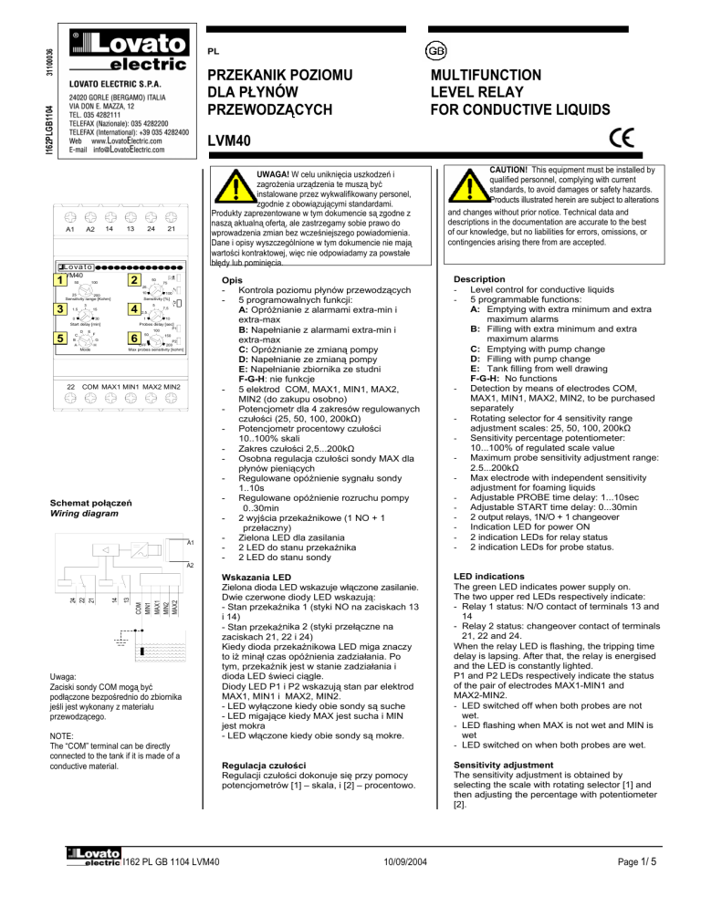
Schemat połączeń
Wiring diagram
A1
13
COM
MIN1
MAX1
MIN2
MAX2
14
24
22
21
A2
Uwaga:
Zaciski sondy COM mogą być
podłączone bezpośrednio do zbiornika
jeśli jest wykonany z materiału
przewodzącego.
NOTE:
The “COM” terminal can be directly
connected to the tank if it is made of a
conductive material.
I162 PL GB 1104 LVM40
CAUTION! This equipment must be installed by
qualified personnel, complying with current
standards, to avoid damages or safety hazards.
Products illustrated herein are subject to alterations
and changes without prior notice. Technical data and
descriptions in the documentation are accurate to the best
of our knowledge, but no liabilities for errors, omissions, or
contingencies arising there from are accepted.
Opis
- Kontrola poziomu płynów przewodzących
- 5 programowalnych funkcji:
A: Opróżnianie z alarmami extra-min i
extra-max
B: Napełnianie z alarmami extra-min i
extra-max
C: Opróżnianie ze zmianą pompy
D: Napełnianie ze zmianą pompy
E: Napełnianie zbiornika ze studni
F-G-H: nie funkcje
- 5 elektrod COM, MAX1, MIN1, MAX2,
MIN2 (do zakupu osobno)
- Potencjometr dla 4 zakresów regulowanych
czułości (25, 50, 100, 200kΩ)
- Potencjometr procentowy czułości
10..100% skali
- Zakres czułości 2,5...200kΩ
- Osobna regulacja czułości sondy MAX dla
płynów pieniących
- Regulowane opóźnienie sygnału sondy
1..10s
- Regulowane opóźnienie rozruchu pompy
0..30min
- 2 wyjścia przekaźnikowe (1 NO + 1
przełaczny)
- Zielona LED dla zasilania
- 2 LED do stanu przekaźnika
- 2 LED do stanu sondy
Description
- Level control for conductive liquids
- 5 programmable functions:
A: Emptying with extra minimum and extra
maximum alarms
B: Filling with extra minimum and extra
maximum alarms
C: Emptying with pump change
D: Filling with pump change
E: Tank filling from well drawing
F-G-H: No functions
- Detection by means of electrodes COM,
MAX1, MIN1, MAX2, MIN2, to be purchased
separately
- Rotating selector for 4 sensitivity range
adjustment scales: 25, 50, 100, 200kΩ
- Sensitivity percentage potentiometer:
10...100% of regulated scale value
- Maximum probe sensitivity adjustment range:
2.5...200kΩ
- Max electrode with independent sensitivity
adjustment for foaming liquids
- Adjustable PROBE time delay: 1...10sec
- Adjustable START time delay: 0...30min
- 2 output relays, 1N/O + 1 changeover
- Indication LED for power ON
- 2 indication LEDs for relay status
- 2 indication LEDs for probe status.
Wskazania LED
Zielona dioda LED wskazuje włączone zasilanie.
Dwie czerwone diody LED wskazują:
- Stan przekaźnika 1 (styki NO na zaciskach 13
i 14)
- Stan przekaźnika 2 (styki przełączne na
zaciskach 21, 22 i 24)
Kiedy dioda przekaźnikowa LED miga znaczy
to iż minął czas opóźnienia zadziałania. Po
tym, przekaźnik jest w stanie zadziałania i
dioda LED świeci ciągle.
Diody LED P1 i P2 wskazują stan par elektrod
MAX1, MIN1 i MAX2, MIN2.
- LED wyłączone kiedy obie sondy są suche
- LED migające kiedy MAX jest sucha i MIN
jest mokra
- LED włączone kiedy obie sondy są mokre.
LED indications
The green LED indicates power supply on.
The two upper red LEDs respectively indicate:
- Relay 1 status: N/O contact of terminals 13 and
14
- Relay 2 status: changeover contact of terminals
21, 22 and 24.
When the relay LED is flashing, the tripping time
delay is lapsing. After that, the relay is energised
and the LED is constantly lighted.
P1 and P2 LEDs respectively indicate the status
of the pair of electrodes MAX1-MIN1 and
MAX2-MIN2.
- LED switched off when both probes are not
wet.
- LED flashing when MAX is not wet and MIN is
wet
- LED switched on when both probes are wet.
Regulacja czułości
Regulacji czułości dokonuje się przy pomocy
potencjometrów [1] – skala, i [2] – procentowo.
Sensitivity adjustment
The sensitivity adjustment is obtained by
selecting the scale with rotating selector [1] and
then adjusting the percentage with potentiometer
[2].
10/09/2004
Page 1/ 5
Ta metoda ułatwia precyzyjne regulowanie
czułości w szerokim zakresie (2,5..200Kohm).
Ustawiając potencjometr [6] w pozycji OFF,
uzyskujemy czułość, ustawioną na [1] i [2], dla
wszystkich sond. Jeśli natomiast ustawimy
jakąś wartość na potencjometrze [6], będą z
nią pracować sondy MAX1 i MAX2, natomiast
sondy MIN1 i MIN2 będą pracować z czułością
ustawioną [1] i [2].
W takich warunkach, przekaźnik może
pracować z płynami pieniącymi lub mającymi
pływającą powierzchnię i wymagają wyższej
czułości dla reszty płynu.
This method facilitates the fine adjustment and
consents, at the same time, to have a wide
range, 2.5...200kOhm.
With potentiometer [6] in OFF position,
sensitivity, adjusted with [1] and [2], is common to
all the electrodes. Instead with [6] at one of the
scale values, electrodes MAX1 and MAX2 work
with sensitivity fixed by [6] while electrodes MIN1
and MIN2 continue to work with the value set by
[1] and [2].
In these conditions, the relay can operate with
foaming liquids or which have a surface-floating
layer and requires a higher sensitivity respect to
the rest of the liquid.
Opóźnienie zadziałania
Używając potencjometru [3] możemy ustawiać
opóźnienie rozruchu pompy od 0 do 30 min.
START delay
Using potentiometer [3], the pump starting delay
can be adjusted between 0 and 30 minutes.
Opóźnienie sondy
Używając potencjometru [4] ustawiamy
opóźnienie sondy od 1 do 10 sec, gdy sonda
jest mokra lub sucha, by uniknąć zadziałania w
wyniku efektu falowania.
PROBE delay
With potentiometer [4], the time delay, 1...10
seconds range, can be regulated when the probe
is wet or not wet, to avoid inconvenient tripping
caused by liquid motion.
Rodzaje pracy
Potencjometrem [5] możemy wybierać rodzaj
pracy, opisane poniżej.
Przy wyborze rodzaju pracy gdy przekaźnik jest
zasilony wszystkie diody migają i urządzenie
kasuje się zaczynając prace w nowym trybie.
Po wyborze trybu pracy, sondy muszą być
podłączone jak pokazano na odpowiednim
wykresie działania poniżej.
Operating modes
Using rotating selector [5], the operating modes,
described below, can be chosen.
The selector adjustment while the unit is powered
causes all the LEDs to flash and the unit to reset;
a subsequent restarting takes place in the new
operating mode.
On the basis of the operating mode selected, the
electrodes must be mounted as illustrated in the
corresponding “Operational diagram” below.
TYP A – opróżnianie + alarmy
Pompa 1 (przekaźnik 1) jest w stanie
zadziałania kiedy sonda MAX1 jest mokra i w
stanie niezadziałania kiedy sonda MIN1 jest
sucha. Przekaźnik alarmowy (przekaźnik 2) jest
normalnie w stanie zadziałania i przechodzi w
stan niezadziałania kiedy poziom przekroczy
MAX2 lub jest poniżej MIN2.
By uzyskać tylko jeden alarm MAX, podłączyć
MIN2 do COM.
By uzyskać tylko jeden alarm MIN, nie
podłączać wejścia MAX2.
Symulacyjne zadziałanie przekaźników można
uzyskać przez podłączenie MAX2 do COM i
pozostawienie odłączonej MIN2. W ten sposób
oba przekaźniki są aktywowane kiedy sonda
MAX1 jest mokra i dezaktywowane kiedy
sonda MIN1 jest sucha.
Zmiany podłączeń należy dokonywać przy
wyłączonym przekaźniku.
COM
MIN2
MIN1
MAX1
MAX2
MODE A – Emptying + alarms
The pump (Relay 1) is activated when the level
wets the MAX1 probe and is deactivated when
the MIN1 probe is no longer wet.
The alarm relay (Relay 2) is energised in normal
operating conditions and is de-energised when
the level exceeds MAX2 or is lower than MIN2.
To obtain one MAX alarm only, MIN2 input must
be connected to COM.
To obtain one MIN alarm only, the MAX2 input
must not be connected.
The simultaneous activation of the relays can be
possibly obtained by connecting the MAX2
electrode to COM and leaving MIN2 electrode
disconnected. In this way, both relays are
activated when the level wets the MAX1 probe
and deactivates when the MIN1 probe is no
longer wet.
The connections must be changed only when the
level relay is switched off.
Wykres działania (TYP A) - Operational diagram (MODE A)
(2)
Relè 1/
14
13
Relè 2/
24
21
22
ON
(1)
(1)
(2)
(1)
(2)
(2)
A2
A1
(1) Opóźnienie sondy + opóźnienie startu / PROBE delay + START delay
(2) Opóźnienie sondy / PROBE delay
I162 PL GB 1104 LVM40
10/09/2004
Page 2/ 5
TYP B – napełnianie + alarmy
Pompa 1 (przekaźnik 1) jest w stanie
zadziałania kiedy sonda MIN1 jest sucha i w
stanie niezadziałania kiedy sonda MAX1 jest
mokra.
Przekaźnik alarmowy (przekaźnik 2) jest
normalnie w stanie zadziałania i przechodzi w
stan niezadziałania kiedy poziom przekroczy
MAX2 lub jest poniżej MIN2.
By uzyskać tylko jeden alarm MAX, podłączyć
MIN2 do COM.
By uzyskać tylko jeden alarm MIN, nie
podłączać wejścia MAX2.
Symulacyjne zadziałanie przekaźników można
uzyskać przez podłączenie MAX2 do COM i
pozostawienie odłączonej MIN2. W ten sposób
oba przekaźniki są aktywowane kiedy sonda
MIN1 jest sucha i dezaktywowane kiedy sonda
MAX1 jest mokra.
Zmiany podłączeń należy dokonywać przy
wyłączonym przekaźniku.
MODE B – Filling + alarms
The pump (Relay 1) is activated when the level
does not wet the MIN1 probe and is deactivated
when the MAX1 probe is wet.
The alarm relay (Relay 2) is energised in normal
operating conditions and is de-energised when
the level exceeds MAX2 or is below MIN2.
To obtain MAX alarm only one, connect the MIN2
input to COM.
To obtain one MIN alarm only, do not connect the
MAX2 input.
The simultaneous activation of the relays can be
possibly obtained by connecting the MAX2
electrode to COM and leaving theMIN2 electrode
disconnected. In this way, both relays are
activated when the level does not wet the MIN1
probe and are deactivated when the MAX1 probe
is wet.
The connections must be changed only when the
level relay is switched off.
COM
MIN2
MIN1
MAX1
MAX2
Wykres działania (TYP B) - Operational diagram (MODE B)
(1)
(2)
(1)
(2)
(2)
(2)
(2)
(2)
MODE C – Emptying + pumps swapping
Relè 1/
14
13
Relè 2/
24
21
22
ON
A2
A1
(1) Opóźnienie sondy + opóźnienie startu / PROBE delay + START delay
(2) Opóźnienie sondy / PROBE delay
TYP C – opróżnianie + zamiana pomp
Pompa 1 (przekaźnik 1) jest w stanie
zadziałania kiedy sonda MAX1 jest mokra i w
stanie niezadziałania kiedy sonda MIN1 jest
sucha.
Pompa 2 (przekaźnik 2) jest w stanie
zadziałania kiedy sonda MAX2 jest mokra i w
stanie niezadziałania kiedy sonda MIN2 jest
sucha.
Działanie pompy nieaktywnej uzyskujemy za
każdym razem kiedy poziom nie osiągnie
MAX2.
Minimalny czas zamiany pomp 1 i 2 wynosi 5
sec.
MODE C – Emptying + pump change
Pump 1 (Relay 1) is activated when the level
wets the MAX1 probe and is deactivated when
the MIN1 probe is no longer wet.
Pump 2 (Relay 2) is activated when the level
wets the MAX2 probe and deactivates when the
MIN2 probe is no longer wet.
The changeover between pumps 1 and 2 is
obtained each time a new pump operation is
needed, beginning with both pumps switched off.
The starting of the non-active pump is obtained at
any time when the level wets the MAX2 probe.
A minimum transition time of 5 seconds is always
interposed between the changeover of pump 1
and pump 2.
COM
MIN1
MIN2
MAX1
MAX2
Wykres działania (TYP C) - Operational diagram (MODE C)
(1)
(2)
(1)
(2)
(1)
(1)
(2)
(1)
(1)
Relè 1/ 14
13
. Relè 2/
24
21
22
ON
A2
A1
5 sec
(1) Opóźnienie sondy + opóźnienie startu / PROBE delay + START delay
(2) Opóźnienie sondy / PROBE delay
I162 PL GB 1104 LVM40
10/09/2004
Page 3/ 5
TYP D – napełnianie + zamiana pompy
Pompa 1 (przekaźnik 1) jest w stanie
zadziałania kiedy sonda MIN1 jest sucha i w
stanie niezadziałania kiedy sonda MAX1 jest
mokra.
Pompa 2 (przekaźnik 2) jest w stanie
zadziałania kiedy sonda MIN2 jest sucha i w
stanie niezadziałania kiedy sonda MAX2 jest
mokra.
Działanie pompy nieaktywnej uzyskujemy za
każdym razem kiedy poziom nie osiągnie
MIN2.
Minimalny czas zamiany pomp 1 i 2 wynosi 5
sec.
MODE D – Filling + pump change
Pump 1 (Relay 1) is activated when the level
does not wet the MIN1 probe and is deactivated
when the level wets the MAX1 probe.
Pump 2 (Relay 2) is activated when the level
does not wet the MIN2 probe and is deactivated
when the MAX2 probe is wet.
The changeover between pumps 1 and 2 is
obtained each time a new pump operation is
needed, beginning with both pumps switched off.
The starting of the non-active pump is obtained at
any time when the level does not web the MIN2
probe.
A minimum transition time of 5 seconds is always
interposed between the changeover of pump 1
and pump 2.
COM
MIN2
MIN1
MAX2
MAX1
Wykres działania (TYP D) - Operational diagram (MODE D)
(1)
(2)
(1)
(2)
(1)
(1)
(2)
(1)
Relè 1/ 14
13
5 sec
24
Relè 2/ 21
22
ON
A2
A1
(1) Opóźnienie sondy + opóźnienie startu / PROBE delay + START delay
(2) Opóźnienie sondy / PROBE delay
MODE E – Tank filling + Well drawing +
alarms
This function includes the tank filling using a
pump to draw from a well. MAX1 and MIN1
electrodes are used for the storage tank while
MAX2 and MIN2 electrodes are installed in the
well.
The consent to draw from the well is given when
the MAX2 probe is wet: Contrarily, it is reset
when the MIN2 probe is no longer wet.
When the storage tank is empty, MIN1 probe not
wet and the well consent available, the pump
(Relay 1) can be activated.
The pump is stopped when the MAX1 probe is
wet or when the drawing consent is void because
the well is dry.
The alarm relay (Relay 2) is de-energised when
alarm conditions for empty tank and empty well
are present, that is MIN1 and MIN2 probes are
both not wet.
TYP E – napełnianie zbiornika + opróżnianie
studni + alarmy
Ta funkcja zawiera napełnianie pompy
opróżniającej studnie. Sondy MAX1 i MIN1
służą do kontroli zbiornika, MAX2 i MIN2 do
kontroli studni.
Czerpanie ze studni zaczyn się gdy sonda
MAX2 jest mokra, i odwrotnie, czerpanie jest
zatrzymywane kiedy sonda MIN2 jest sucha.
Kiedy zbiornik jest pusty, sonda MIN1 jest
sucha i studnia napełniona, pompa (przekaźnik
1) może być aktywowana.
Pompa jest zatrzymywana kiedy sonda MAX1
jest mokra lub kiedy studnia jest pusta.
Przekaźnik alarmowy (przekaźnik 2) jest w
stanie niezadziałania kiedy spełnione są
warunki: pusty zbiornik i pusta studnia, tzn.
obie sondy MIN1 i MIN2 są suche.
COM
MIN1
MAX1
Wykres działania (TYP E) - Operational diagram (MODE E)
(1)
(2)
(1)
(2)
(1)
COM
MIN2
MAX2
Serbatoio/
Pozzo/
Relè 1/ 14
13
24
Relè 2/ 21
22
ON
A2
A1
(1) Opóźnienie sondy + opóźnienie startu / PROBE delay + START delay
(2) Opóźnienie sondy / PROBE delay
I162 PL GB 1104 LVM40
10/09/2004
Page 4/ 5
DANE TECHNICZNE
Zasilanie i kontrola
Napięcie znamionowe Ue
Wymiary
Mechanical dimensions
Częstotliwość znamionowa
Zakres działania
Pobór mocy
Rozproszenie mocy
Sondy poziomu
Napięcie na zaciskach sondy
4.2mm
Prąd płynący przez elektrody
104.7
mm
98.3
mm
90.0
mm
45.0
mm
Max długość kabla (Zobacz
Nota 1)
Max pojemność kabla
(Zobacz Nota 1)
Czas opóźnienia
Opóźnienie sondy
Opóxnienie zadziałania
Przekaźnikwyjściowy
Liczba wyjść
Typ
Napięcie znamionowe
Max napięcie przełączania
Normy IEC/EN 60947-5-1
53.5mm
Trwałość elektryczna
Trwałość mechaniczna
Napięcie izolacji
Znamionowy impuls napięcia
wytrzymania Uimp
Znamionowe napięcie
izolacji Ui
Napięcie izolacji pomiędzy
zaciskami
Podwójna izolacja
Zasilanie/przekaźnik/sonda
5.0mm
43.7mm
58.0mm
59.9mm
Warunki otoczenia
Temperatura pracy
Temperatura składowania
Względna wilgotność
Połączenia
Typ zacisków
Typ kabli
Moment obrotowy docisku
Obudowa
Wersja
Montaż
Materiał
Stopień ochrony
0 – 24VAC
0 – 220…240VAC
0 - 380…415VAC
50/60Hz ±5%
0,85…1.1 Ue
4,5VA
2,8W
5 Vpp
0,4mA max
800m max / czułość 25 kΩ
400m max / czułość 50 kΩ
200m max / czułość 100 kΩ
100m max / czułość 200 kΩ
400nF max / czułość 25kΩ
200nF max / czułość 50kΩ
100nF max / czułość 100kΩ
50nF max / czułość 200kΩ
1…10sec
0…30min
2
1 NO + 1 przelaczny
250VAC
400VAC
AC1 8A-250VAC / B300
105 cykli
30x106 cykli
6kV
415VAC
2,5kVAC
≤ 250VAC
-20 ... +60°C
-30 ... +80°C
<90%
śrubowy
0.2 - 4.0 mm2
(24 - 12 AWG)
0,8Nm (7lbin)
3 moduły (DIN 43880)
Szyna 35mm (EN60715)
Lub za pomocą śrub używając
klipsów
Poliammide
IP40 od przodu
IP20 na zaciskach
260g
Waga
Certyfikaty
cULus ( w trakcie)
Normy i standardy
IEC/EN 60255-6, IEC/EN 60255-5, IEC/EN 61010-1
IEC/EN 61000-6-2, IEC/EN 61000-6-3,
IEC/EN 60068-2-6, IEC/EN 60068-2-27,
IEC/EN 60028-2-61, DIN 43880,
UL 508/CSA C22.2_N14-95 .
Nota 1
Długość kabla kalkulowana przy użyciu kabla: 600V,
3–żyłowy, 0,75 m m².
Długość kabla może być redukowana jeśli jeśli przekrój kabla
jest większy i jeśli użyto kabla o większej ilości żył.
I162 PL GB 1104 LVM40
10/09/2004
TECHNICAL CHARACTERISTICS
Power supply and control circuit
Rated operational voltage Ue
Rated frequency
Operating range
Power consumption
Power dissipation
Electrode circuit
Voltage at electrode
terminals
Current flowing through
electrodes
Maximum cable length
(See Note 1 below)
Maximum cable capacitance
(See Note 1 below)
Time delays
Probe tripping delay
Relay energising delay
Output relays
Number of relays
Type of output
Rated operating voltage
Maximum switching voltage
IEC/EN 60947-5-1
designation
Electrical life
Mechanical life
Insulation voltage
Rated impulse withstand
voltage Uimp
Rated insulation
voltage Ui
Insulation voltage between
two groups of contacts
Double insulation:
Probe/supply
Probe/relay
Ambient conditions
Operating temperature
Storage temperature
Relative humidity
Connections
Type of terminals
Conductor cross section
Tightening torque
Housing
Version
Mounting
Material
Degree of protection
0 – 24VAC
0 – 220…240VAC
0 – 380…415VAC
50/60Hz ±5%
0.85…1.1 Ue
4.5VA max
2.8W max
5 Vpp
0.4mA max
800m max / sensitivity 25 kΩ
400m max / sensitivity 50 kΩ
200m max / sensitivity 100 kΩ
100m max / sensitivity 200 kΩ
400nF max / sensitivity 25kΩ
200nF max / sensitivity 50kΩ
100nF max / sensitivity 100kΩ
50nF max / sensitivity 200kΩ
1…10sec
0…30min
2
1 N/O + 1 changeover
250VAC
400VAC
AC1 8A-250VAC /
B300
105 ops
30x106 ops
6kV
415VAC
2.5kVAC
≤ 250VAC
-20 ... +60°C
-30 ... +80°C
<90%
Fixed
0.2 - 4.0 mm2
(24 - 12 AWG)
0.8Nm (7lbin)
3 modules (DIN 43880)
on 35mm DIN rail (IEC/
EN60715) or by screws using
extractible clips
Polyamide
IP40 on front
IP20 at terminals
260g
Weight
Certifications
cULus ( pending)
Compliant with standard
IEC/EN 60255-6, IEC/EN 60255-5, IEC/EN 61010-1
IEC/EN 61000-6-2, IEC/EN 61000-6-3,
IEC/EN 60068-2-6, IEC/EN 60068-2-27,
IEC/EN 60028-2-61, DIN 43880,
UL 508 and CSA C22.2_N°14-95.
Note 1
Cable length is calculated using 600V, 3-core, 0.75mm²
section cables.
The total cable length can be reduced if cable section is
greater or a higher number of cores is used.
Page 5/ 5

